Pssst - want some high-tech protection for your home office, or a secret lock for your "workshop" (ok, you got me, it's actually an arcade/dungeon) That the children will not be able to realize? We've got you covered. Let's build a DIY smart lock that automatically detects when you're there, and locks itself when you're not.
How does it work? NOBODY KNOWS! Or more specifically, Bluetooth.
Your smartphone is a powerful device that constantly reveals information about itself to the outside world; One way to do it is bluetooth..
In discovery mode, it transmits a unique identification number, but even when not specifically allowed to be discovered, anything that knows the address can try to ping it. If a response is heard, that would indicate if it is in range or not.
We'll be setting up a Raspberry Pi with a Bluetooth adapter to constantly be aware when your smartphone is out of range, and when it is, the relay will activate and close the door.
Bluetooth is critical to this project, so let's start by installing some Bluetooth support and testing our adapter. You can do this directly from the Pi or from SSH remotely (how to configure Windows to SSH into your Pi. How to configure your Raspberry Pi for headless use with SSH How to configure your Raspberry Pi for headless use with SSH than the Raspberry The Pi can accept SSH commands when connected to a local network (either over Ethernet or Wi-Fi), allowing you to easily set it up. The benefits of SSH go beyond upsetting everyday discovery... Read More) .
sudo apt-get install bluez python-bluezInsert your dongle if you haven't already, and let's take a look at what it's reporting.
hcitool devIf you have something on the checkout list, you're good to go. Next, we'll use a Python script to poll nearby Bluetooth devices and get the device's unique address. We only need to do this once for each device.
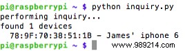
wget https://raw.githubusercontent.com/karulis/pybluez/master/examples/simple/inquiry.py python inquiry.pyIf you see “0 devices found”, you may not have a compatible USB Bluetooth dongle or your smartphone may not be discoverable. Don't despair though:I found that I had to open the Bluetooth settings page on my iPhone to put it into discoverable mode, then it happened :
Great, now let's create the first stage of our software that does the detection. Create a Python application called detect.py , and open it with nano.
nano detect.pyPaste in this sample code:
#! / usr / bin / python importa el tiempo de importación de bluetooth mientras sea Verdadero: imprima "Checking" + time.strftime ("% a,% d% b% Y% H:% M:% S", time.gmtime ()) result = bluetooth.lookup_name ('78: 7F: 70: 38: 51: 1B ', timeout = 5) if (result! = None): imprime "User present" else: print "User out of range" time.sleep ( 10) and wrap the following line with the address of your Bluetooth device:
resultado = bluetooth.lookup_name ('78: 7F: 70: 38: 51: 1B ', tiempo de espera = 5)press CTRL-X and AND to close and save. Run the same code and you will see something like this:
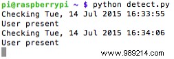
The code should be very simple to understand, even if you've never touched Python before:it's looking for a particular Bluetooth device every 10 seconds and prints a different message depending on whether it's found or not. Toggle Bluetooth on your phone to simulate movement in and out of range (probably about 4m actually). You can decrease or increase the time between scans, but I felt like 10 seconds was a reasonable amount of time to potentially have to wait for the door to unlock, which is where we're going with this whole project after all.
I should add, I don't know about the power consumption of doing this, but I'm guessing that pinging a device more often will necessarily consume more power. I haven't seen any obvious performance issues in testing, but if battery life is a major concern for you, consider having a switch inside your office that turns the scan cycle on and off, so once inside, you can pause the lock. system, then turn scanning back on when you exit.
Congratulations, you now have a Python application that knows when you're in range, so we can start acting on that.
Before continuing, you need to figure out which table mode you are going to use. There is no right or wrong answer, it only affects whether you specify the literal pin number or the virtual GPIO pin number.
The default is to use the literal pin number ("board mode"), starting with pin 1 on the bottom left (if you look down on the Pi with USB ports on the right). Pin 2 is right on top of that.
However, if you have a GPIO breakout (“shoemaker”), the labels you have are of an alternate mode, called “BCM” (Broadcom SOC Channel), and are typically written with GPIO or P prefixing the number. You don't strictly need a GPIO breakout, it just makes things easier. If you don't have a breakout board and don't want to buy one, use this diagram:
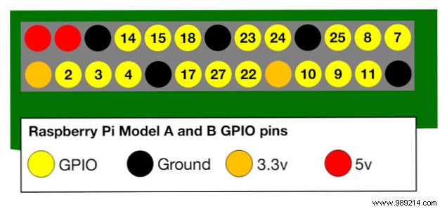
Note that the original Model B Revision 1, Revision 2, and Model B+ and Pi2 have different pin outputs. See this StackExchange question for a correct diagram for your board.
In this project code I am using the BCM GPIO numbering system which corresponds to the Adafruit breakout board I have. Minor modifications are needed if you want to use literal pin mode.
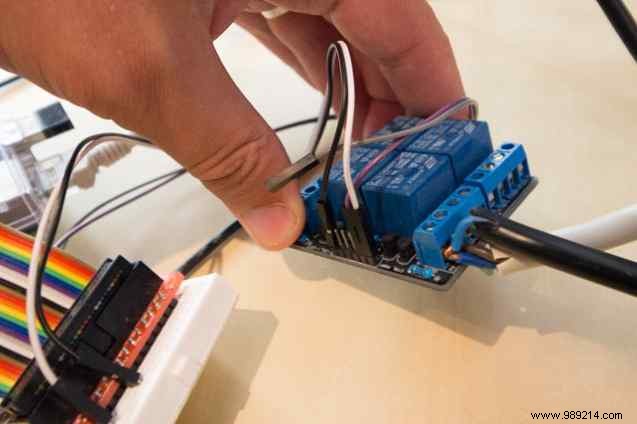
Connect the breakout board, making sure the wire from pins 1 and 2 (the ones on the corner of your Pi) connect to 3v3 and 5V0 on the breakout. You may want to pull out a voltage tester to check this.
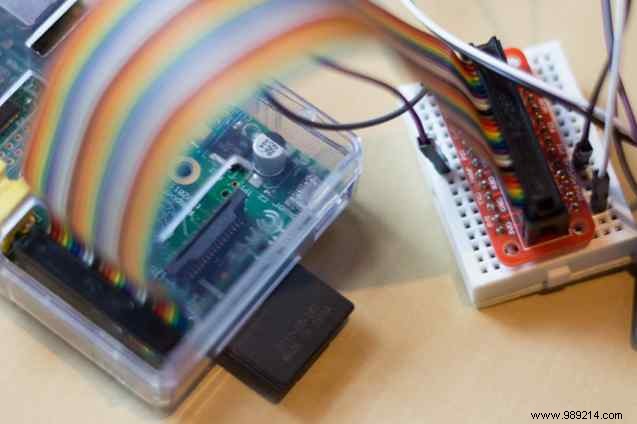
Before proceeding, check to see if anyone else has used your particular relay with the Raspberry Pi (or find one that you know works). Some may require 5V to turn on, but the RPi can only provide 3.3V on the GPIO output pins. By chance the one I'm using is happy with 3.3V, so I didn't need any extra circuitry, just the 5V0 to VCC , GND to GND , and GPIO pin 23 for the first relay input .
My previous tutorial on GPIO Getting Started with GPIO on a Raspberry Pi Getting Started with GPIO on a Raspberry Pi If you thought the Arduino was cool, just wait until you have a Raspberry Pi, these things are awesome. As well as being a fully functional computer, they also have a... Read More didn't need 5V after all).
It is not necessary to connect the electromagnet yet, as you will be able to hear an audible click when the relay is triggered.
Next, we are going to grab some code to interact with the GPIO ports.
We'll start by testing outside of Python to confirm that everything is working on the ports. Install wiringPi, which gives you some useful command line tools.
git clone git: //git.drogon.net/wiringPi cd wiringPi ./buildOnce installed, configure GPIO pin 23 to be an output.
gpio -g modo 23 fueraNow do a quick scan of all ports to confirm
gpio -g readallYou'll have something similar to this, although yours may be longer on a Model B+ or Pi2 as it has more GPIO pins:
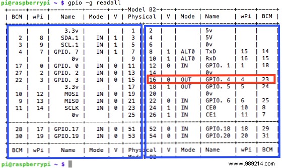
This can be a bit confusing at first, but the table is split down the middle and the order of the columns is reversed on each side. On the far left and far right is the BCM pin number. Since we're using 23, you should see the mode now listed as OUT. This is a handy little command just to get a good idea of what's going on with all your pins at any given time.
To write the pin high or low, just use
gpio -g escribe 23 1 gpio -g escribe 23 0Hopefully if you have the relay wired correctly you will hear it click and go off. If not, don't continue until you've figured out the wiring. Remember that you may need a higher voltage to activate the relay.
Once you have confirmed that the relay and GPIO are working, add the Python modules for the GPIO.
sudo apt-get install python-dev python-rpi.gpioNow let's modify our Python application to turn the relay on or off when the phone is detected. You will find the final code in this Gist. Copy the existing detect.py to a new lock.py , and add the following import and configuration commands:
importar RPi.GPIO como GPIO GPIO.setmode (GPIO.BCM) RELAY = 23 GPIO.setup (RELAY, GPIO.OUT)In the IF statement, add a command to turn the relay on or off. Please note that your relay can operate on a low or high signal, so adjust accordingly after testing.
GPIO.output (RELAY, 1)To run this new version, prefix the command with sudo - GPIO access requires root privileges.
Once you've confirmed that the relay is firing with your proximity sensor, add the electromagnet lock. On the relay side, put the 12V positive to the terminal labeled COM (common), then the positive power input from the electromagnet to the NO terminal (Normally Open, ie. Normally this is not connected to the common terminal , but it will be when you activate the relay ).
Join the ground from the power supply and the electromagnet at the GND terminal.
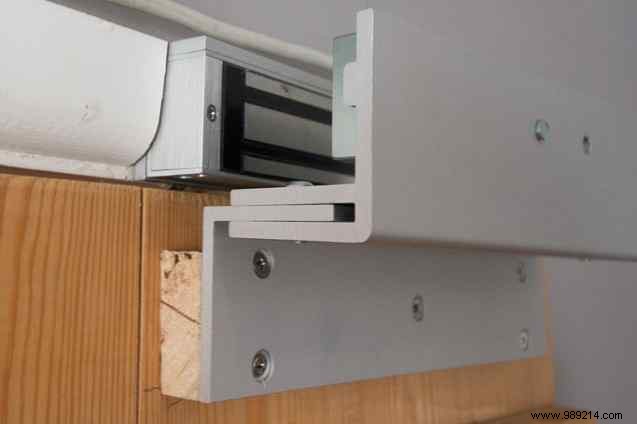
See the mounting instructions that came with your lock; the door should be fairly thick, and it's easier if it opens away from the side you want the lock to be on. Mine was the opposite, so I need the L-shaped mounting bracket as well as an extra piece of wood to increase the thickness of the door.
This was a proof of concept for me to continue with other projects, and really just to keep prying eyes out of my office when I'm not there, it's not designed to be a foolproof security system. For that, you'd need a backup battery to keep the power flowing in case it goes out.
Of course, if someone breaks into your house and goes to the trouble of lowering your power, you probably have the bigger problem that it's a psycho who's out to kill you, rather than a casual thief. You'd also want a physical deadbolt as well as an electronic deadbolt and a really big stick.
Of course, this Bluetooth proximity sensing technique isn't just limited to an automatic door lock, you can also use it to trigger your garage door opener when you get home, or turn on your home theater earlier. to enter the door.
What feature do you think I should add next? Did you have any trouble building this? Let me know in the comments and I'll do my best to help!